Introduction
Bought some cheap USB driven warm-white LEDs off eBay for lighting display cabinets. Turns out it is just normal LED strips with a simple driver in the USB plug. Wanting to unify control of multiple LED strips into a single point I build a simple PWM based LED driver. It is neither constant current nor constant voltage - for the simple LEDs I have it is Good Enough (tm).
Build Details
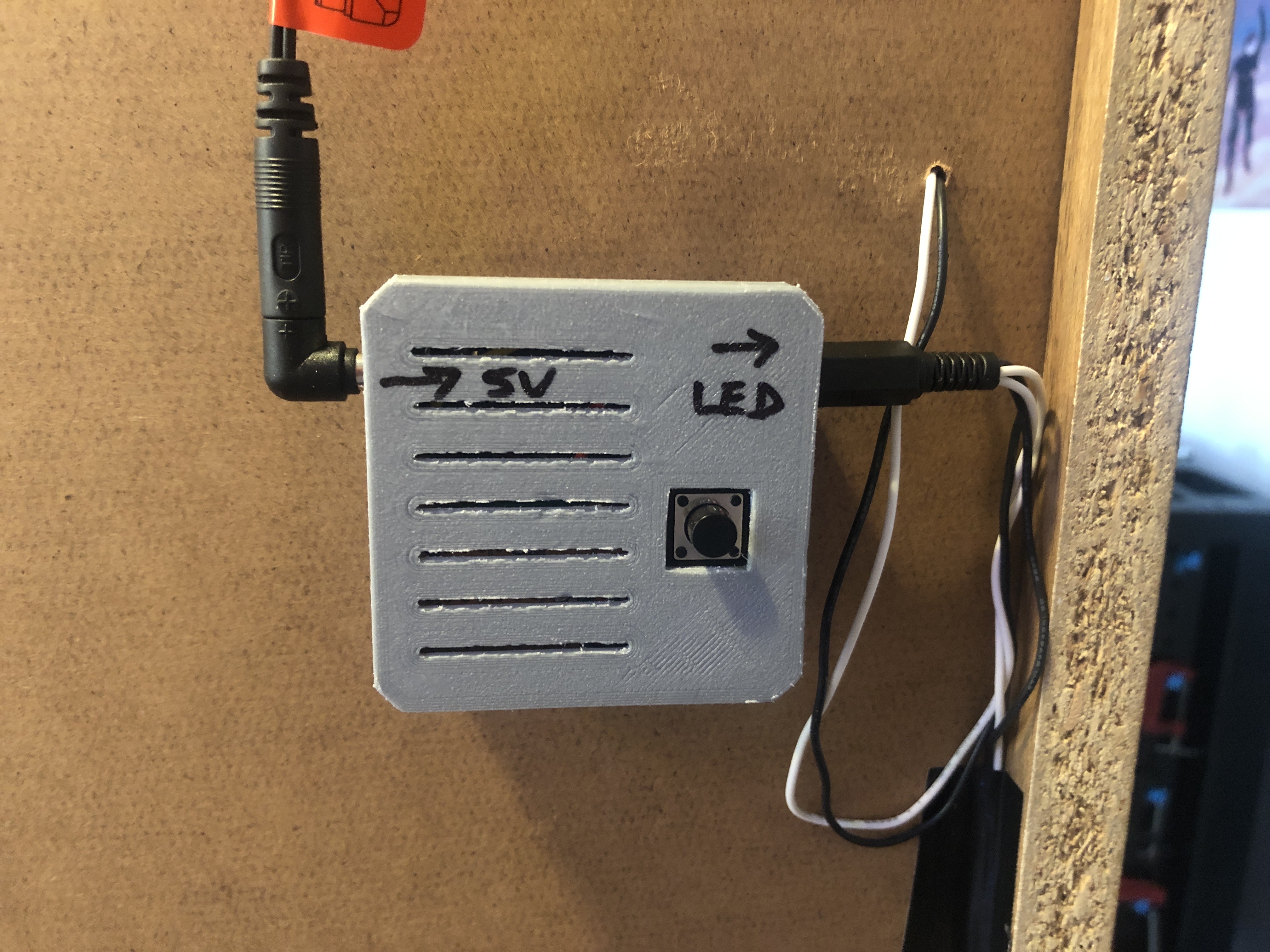
Finished product first, this is the controller mounted on the back of the bookcase where the LED strips are mounted. 5V from a wall plug PSU enters on the left and the LEDs strips are wired in parallel on the right. The single button cycles between on and 3 levels of brightness, with max brightness consuming around 800mA.
With the lid off, the interior layout can be examined. Essentially a single strip board containing all components and socket hardware.

The strip board is very basic: decouple and smoothing capacitor on the top-right; ATTiny13 in the middle in a socket so it can be reprogrammed; BD135 NPN transistor lower middle with base resistor to turn the LEDs on and off; and some resistors detect button press. Could have used the internal pull-up resistors but the construction demanded that the button be wires on the high side.


This project was an opportunity to try a new way of encapsulating projects, namely by using PCB spacer to raise the strip board to top of the enclosure and then constructing a lid to match the button's position. This worked quite well, especially here where the NPN transistor needed some room to dissipate heat. The spacer can be seen in the following photo. Note the vents built into it which line up with the case vents.

The initial case design had the vents (seen below) built in to reduce printing time, turns out they are also very useful for passive cooling of the NPN transistor.

In addition to the vents in the case, vents were also added to the lid to aid cooling after observing that the case as a whole was warm to touch. The goal is for the whole system to operate without fail for the ~8hr period it is designed to operate for before turning itself off due to idle timeout.
Code and CAD
The ATTiny13 was programmed using AVR ISPmkII, PlatformIO and MicroCore. FreeCAD was used to design the enclosure, using the spreadsheet workflow to parameterise dimensions such as case thickness, inteference-fit-tolerance, etc.


To Improve
- Clean up the vents in the case, possibly increase their size and the thickness of the case in that area so it is less flimsy.
- Engrave into the case the LED and 5V labels.
- Screw terminals would have been easier to wire up.